


Disclaimer: I did not make this guide, this is made by TECHPOWERUP.
A Detailed Look Into Power Supplies
Introduction
The abbreviation PSU stands for Power Supply Unit and in the whole article we assume that it is also a Switching Mode Power Supply (SMPS) since in PCs, to the best of our knowledge, only SMPS units are used. A PSU is the heart and a vital part of a system, since it's the one that feeds power to the other components (CPU, VGA, HDD, etc.) If it stops supplying power, for any reason, then nothing else will run since there will be no power to the system. In case of damage to the PSU, there is a possibility that other components may be damaged, too. This is a fact that unfortunately many users ignore, otherwise they would first buy a decent PSU for their systems and then the rest of the components. On the contrary the opposite happens in many cases, users usually acquire all other components and they leave the PSU purchase for last, with the leftover money. If you belong in the category of users that we described above, we are pretty sure that after reading this article you will change tactics. However this article is not addressed only to users that do not know the important role that a PSU plays, but will give valuable information to experienced users, too.
In the beginning of the article, the fundamentals of Switching Power Conversion will be explained and a brief description of the various stages that compose a PSU will be made. In addition, we will make a quick reference to some switching regulator topologies used currently. A few pages dedicated to PSU protections are following and next we take a look at ATX, EPS and 80 PLUS specifications. Finally, in Appendix A we make a quick reference to the most significant electronic components currently used not only in PSU manufacturing but also in every modern electronics device. So you will learn the basic concepts of inductors, capacitors, resistors, transistors and diodes, in order to get familiar with them and understand better some concepts discussed in this article.
As you can imagine it's going to be an interesting and highly informative journey to the PSU world, so join us!
SPC and the Various Stages of a Power Supply
All PSUs that power every PC system today utilize Switching Power Conversion (SPC). The principle of SPC is quite simple, energy is drawn from the power grid, then it's chopped up with a high frequency in smaller energy packets and finally it's transferred with the help of components like capacitors and inductors. In the end all energy packets are merged and after some rectification processes energy is flowing smoothly from the output. So in PSUs we have as input 100–230V AC wall power (AC voltage and frequency differs from region to region) and several outputs that supply regulated DC (Direct Current), which are of course, always the same regardless the country/region. An interesting fact is that as the switching frequency increases the size of the energy packets is getting smaller; thereby the size of components (inductors and capacitors) that store and transfer those packets is also reduced. Finally, a PSU that utilizes SPC is called Switching Mode Power Supply or SMPS.
The two major advantages of an SMPS compared to a Linear Power Supply that uses a totally different design are drastically reduced size and weight and higher efficiency that can easily exceed 90%. On the other hand, the most significant drawbacks of an SMPS are its complexity and the production of Electromagnetic / Radio Frequency Interference (EMI/RFI) that makes necessary the use of an EMI filter (some of you may also know it as transient filtering stage because its role is twofold) and RFI shielding.
The figure above shows the block diagram of an SMPS, there are seven main components that turn AC wall power into several DC voltages used by the components in your computer.
*EMI/Transient Filter: Suppress incoming and out coming EMI/RFI and protects from voltage spikes
*Bridge Rectifier: Rectifies the AC power stream to DC
*APFC: Controls the current supplied to the PSU so that the current waveform is proportional to the mains boltage waveform
*Main Switches: Chop the DC signal to very small energy packets, with high frequency
*Transformer: Isolates primary from secondary side and converts (steps down) the voltage
*Output Rectifiers & Filters: Generate the DC outputs and filter them
*Protection Circuits: Shut down the PSU when something goes wrong
*PWM Controller: Adjusts the duty cycle of the main switches, in order to keep steady output voltage under all loads
*Isolator: Isolates the voltage feedback that comes from the DC outputs and heads to the PWM controller
The part of the SMPS before the power transformer is called “primary” side and the part after it “secondary” side.
In the following pages we will analyze all these individual stages that compose a power supply, in more detail.
EMI/Transient Filtering Stage
The problem with PSUs is that their switching transistors produce EMI/RFI that could seriously affect other electronic devices in the house. Also we must protect the PSU from incoming noise and voltage spikes coming out of the power grid, so the role of this stage is twofold and serves as protection in both directions.
Noise can be classified into two types, according to the conduction mode: Common Mode Noise (CMN) and Differential Mode Noise (DMN).
1. CMN is electrical interference with reference to the ground or common wire. It consists of high frequency spikes and comes from faulty wires or from EMI/RFI of nearby devices. Common mode choke coils along with Y capacitors are used to suppress CMN.
2. DMN represents the noise that is measured between two lines with respect to a common reference point, excluding common-mode noise. To suppress DMN, X capacitors are placed across the lines.
The EMI/Transient filter in PSUs is always placed before the bridge rectifier, because in this position it also suppresses the noise coming from the bridge's diodes (yes, even those produce noise, especially at the moment they are turning off). The necessary parts for a proper EMI/Transient filter are two Y and two X capacitors, two coils, an MOV (Metal Oxide Varistor) and a fuse. Very briefly an MOV is a voltage-dependent resistor that protects the PSU/system from voltage spikes coming from the power grid.
However, especially in low-end PSUs, manufacturers omit some components in order to save money. Usually the first to be left out is the MOV. If your PSU does not have an MOV in the EMI/Transient filter then you should always operate it along with a surge suppressor or a UPS, otherwise a spike could damage permanently not only the PSU but your system too.
Bridge Rectifier
The AC power stream, after it passes the EMI/Transient filter is rectified by one or more bridge rectifiers. So AC is converted to DC with increased voltage (e.g. if we have 230V input then the DC output of the bridge rectifier will be v2 × 230= 325.27V DC). Afterwards the DC signal is fed to the APFC stage.
Active Power Factor Correction (APFC)
Before we talk about the Power Factor Correction stage let's take a quick look at the concept of power factor. Power factor is defined as the ratio of real power to apparent power (kW/kVA) and power is the product of voltage and current (P = V × I).
There are two basic types of loads, resistive (the load consists only of resistors) and reactive (the load consists of inductors, capacitors or both).
In a system with only linear load both current and voltage curves are sinusoidal (the sine wave or sinusoid is a mathematical function that describes a smooth repetitive oscillation @ http://en.wikipedia.org/wiki/Sine_wave ). If the load is purely resistive then both current and voltage reverse their polarity at the same time (the phase angle between voltage and current is 0 degrees), so at every instant the product of voltage and current is positive, meaning that the "direction" of energy flow does not reverse, so only real power is transferred to the load.
In case that the load is purely reactive, there is a time shift (maximum theoretically 90 degrees, typical 45 degrees) between voltage and current so the product of these two for half of each cycle is positive and for the other half is negative (when voltage is at its peak, either positive or negative, current is zero and vice-versa). Thus, on average as much energy flows to the load as flows back to the source (power grid). If we analyze a whole cycle then we will see that there is no net energy flow and only reactive energy flows since there is no net transfer of energy towards the load.
However both scenarios above are only theoretical, as in real life all loads/circuits present resistance, inductance and capacitance at the same time, so both real and reactive power will flow to them. Apparent power is the vector sum of real and reactive power or the product of the root-mean-square of voltage and current. As we already mentioned above, power factor is the ratio between real and apparent power. Ideally we want the power factor to be close to 1. Here we must note that residential consumers pay only for the real power (Watts) they use and not for apparent power. On the contrary business consumers (e.g. factories) pay for apparent power usage, too.
Although we residential consumers do not pay for apparent power, in order to minimize apparent power usage the EU standard EN61000-3-2 states that all switched-mode power supplies with output power of more than 75 W must include passive PFC, at least. In addition 80 PLUS power supply certification requires a power factor of 0.9 or more. Some years ago many PSU manufacturers used Passive PFC (PPFC) in their products. PPFC uses a filter that passes current only at line frequency, 50 or 60 Hz, so the harmonic current is reduced and the non-linear load is transformed to a linear one. Then with the usage of capacitors or inductors the power factor can be brought close to unity. The downfalls of PPFC are the smaller attained power factors compared to APFC and the need for a voltage doubler, for the PSU to be compatible with 115/230V (the proper voltage is manually selected via a switch near the AC input). On the other hand passive PFC has higher efficiency compared to active PFC!
Active PFC is basically an AC/DC converter which controls the current supplied to the PSU via PWM (Pulse Width Modulation). At first the AC voltage is rectified by the bridge rectifier. Then the PWM triggers the APFC MOSFETs (usually two) which separates the intermediate DC voltage into constant pulse sequences. These pulses are smoothened by the smoothing capacitor and are fed to the main switches. Right before the smoothing capacitor we always find an inductor (coil) that has the ability to limit the sudden rise of current without dissipating energy, because it's a reactive component. This coil is necessary because all capacitors that are connected directly to a DC signal show uncontrolled inrush current, so the inductor limits this inrush. In addition sometimes there is also a thermistor used with active PFC to further limit the inrush current especially in the switch-on phase of the PSU, where the smoothing capacitor is fully discharged.
In active PFC two different types of control are mostly used, Discontinuous Conduction Mode (DCM), where the PFC MOSFETs are turned on only when the inductor current has reached zero and Continuous Conduction Mode (CCM) where the MOSFETs are turned on when inductor current is still above zero and therefore all reverse recovery energy is dissipated in the MOSFETs. In the APFC stage of PSUs the second mode (CCM) is mostly used since it is ideal for over 200W output power, because it offers the lowest peak to average current ratio for the converter throughput power. The main drawbacks of CCM are the losses and EMI generation associated with the turn-off of the boost diode (the reverse recovery currents of the diode causes significant power dissipation to the MOSFETs and increased EMI). Because of that we usually see an X capacitor after the bridge rectifier.
Main Switches – Transformer
The main switches operate in two modes only, ON (fully conduction) and OFF (fully non-conduction) and chop the DC signal, coming from the smoothing capacitor, into pulses whose amplitude is the magnitude of the input voltage and whose duty cycle is controlled by a switching regulator controller (Marty Brown – Power Supply Cookbook). Thus the DC signal is converted to an AC rectangular waveform that is fed to the transformer. The latter steps down the voltage which feeds the secondary rectifiers that generate all DC outputs (+12V, 5V, 3.3V, 5VSB, -12V). The transformer also plays the role of an isolator between the primary and the secondary side.
When the switches are ON there is zero voltage across them (theoretically) and when they are OFF we have zero current through them. So always the product V × I is zero. This means that there is no power loss on the switches. However this represents an ideal situation and in real life there are power losses since there is no transistor/MOSFET than can switch instantly. There is always a small period that a transistor (switch) is between ON and OFF state (also called linear region) and during this period the V × I product is not zero. Because of that all MOSFETs in a PSU (and not only) are cooled down by heatsinks and a fan (although there are some PSUs that use only passive cooling).
Output Rectifiers and Filters
The roles of output rectifiers and filters are, as their names state, to rectify and filter the high frequency switching waveform created by the switches (MOSFETs) and fed through the secondary of the main transformer(s). In this stage we meet two types of rectification designs, passive and synchronous. In the first Schottky Barrier Rectifiers (SBRs) are used and in the latter MOSFETs take the place of SBRs. In synchronous rectification efficiency is increased since we get rid of the forward voltage drops of SBRs. To make this crystal clear let's give an example. A typical SBR has 0.5V voltage drop so if we want to conduct 40A then we have 40 × 0.5 = 20W. Now if we use a MOSFET instead of an SBR and assuming that the MOSFET's RDS(on) is 3 mO then we have 40 × 40 × 0.003 = 4.8W. This results in 15.2W less power dissipation and 24% increase in efficiency.
Besides the two above designs sometimes a hybrid one, called semi-synchronous design, may be used. In semi-synchronous MOSFETs and SBRs are used to reduce cost and increase the efficiency above passive design's levels.
The generation of -12V is done with the usage of a conventional diode, since we do not demand much power from this rail (below 1A in most cases). For 5VSB a completely independent circuit with a transformer is usually used, since 5VSB are working continuously even when the PSU is OFF (in standby mode). For the generation/filtering of the main outputs (+12V, 5V and 3.3V) there are three types of regulation. Group regulation, independent regulation and DC-DC conversion. We will analyze each one of them in the below paragraphs.
Group regulation is usually used in low capacity PSUs and budget ones. A fast way to identify group regulation is by checking the number of coils used in the secondary side. If you find only two then group regulation is present. The bigger coil is used for 12V/5V and the smaller one for 3.3V. In this regulation type +12V and 5V are generated together and both of them feed back their output voltage error to the regulator controller. This means that if the load is unbalanced between the rails, then the regulator controller has a really hard time to properly implement regulation (e.g. if the load at +12V is high and at 5V is low then the voltage on the second rail will be raised because the regulator controller tries to raise the +12 rail voltage, but since the latter is connected to 5V then both of them are raised.) This is why most group regulated PSUs fail to keep their rails within +/-5% tolerance at Crossload tests. In group regulation the 3.3V rail is usually regulated by a mag-amp post-regulator from 5V or from 12V (scarcely).
Independent regulation is used in higher capacity and performance PSUs where cost comes in second place. In this type of regulation all main DC outputs have their independent regulation circuit and unbalanced loads do not cause problems to the rails' voltages. The +12V rail is regulated by the main regulator controller and 5V/3.3V by mag-amp post-regulators. You can easily indentify a PSU that uses independent regulation by the number of toroidal coils in its secondary side. If you find three of them (one for each rail) then the PSU uses independent regulation.
Now in many contemporary PSUs the generation of the minor rails is done with the use of buck -step down- converters (DC-DC converters or Voltage Regulation Modules – VRMs). In these PSUs 5V/3.3V are generated from the +12V directly. This has a positive impact on efficiency and in cross-regulation. Here we must note, PSUs that utilize DC-DC conversion are independent regulated too.
A last note before we move to the next stage, the toroidal chokes located after the rectifiers take part not only in the rectification but also in the filtering process, since they are used for ripple, voltage and current, reduction on the DC outputs. However in PSUs that utilize LLC resonant topologies usually there are no toroidal chokes in the secondary (for +12V generation) and if there is any then it is used only for filtering.
PWM Controller - Isolator
The main purpose of the PWM controller is to maintain a regulated output voltage and control the amount of energy being delivered to the load (system). The aforementioned are accomplished by adjusting the duty cycle of the main switches. The duty cycle can be adjusted from 0 to 100 percent but usually its range is smaller. With great approximation we could say that output voltage is the product of input voltage and duty cycle (Vout = Vin × duty cycle).
The PWM controller uses a voltage reference as the PSUs “ideal” reference to which the output voltage is constantly compared. In the PWM IC there is a voltage error amplifier that performs a high gain voltage comparison between the output voltage and the above-mentioned reference. According to this comparison an error voltage-to-pulse width converter sets the duty cycle in response to the level of the error voltage from the voltage error amplifier. Besides determining the duty cycle of the main switches the PWM controllers usually incorporate and other functionalities, as soft-start circuit which starts the PSU smoothly reducing large inrush currents, over-current amplifier that protects the PSU from overloading, undervoltage lockout that prevents the PSU starting when the voltage within the control IC is too small to drive the main switches etc.
In order for the voltage feedback, from the DC outputs, to reach the voltage error amplifier of the PWM IC an isolated feedback is needed. There are two methods of electrical isolation, optical (optoisolator) and magnetic (transformer). In modern PSUs optoisolators are commonly used. The voltage error amplifier is placed on the secondary side of the optoisolator.
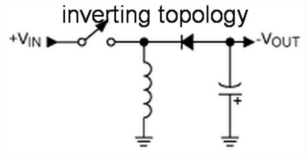
Switching Regulator Topologies used in Contemporary PSUs
According to the peak current that will pass from the main switches, the desired efficiency levels, the maximum operating voltage across the switches the cost etc. a manufacturer has several switching regulator topologies at his disposal.
below you will find a table that compares several switching regulator topologies (Marty Brown: Power Supply Cookbook)
Lately, many PSUs use the LLC resonant topology. This topology, utilizing a resonant combination of inductors and capacitors, shapes the voltage and current waveforms in switching MOSFETs allowing for soft (zero voltage) switching which by its turn leads to RFI and EMI reduction and minimized switching losses, so we gain increased efficiency. Utilizing LLC resonant converters higher switching speeds along with efficiencies of 93 – 95% can be achieved.
Finally, here you will find a very informative pdf file that describes many commonly used topologies @ http://www.techpowerup.com/articles/...topologies.pdf
Results 1 to 10 of 19
-
04-14-2011, 01:30 AM #1C.I.A.


- Join Date
- Oct 2004
- Gender

- Posts
- 2,339
 A Detailed Look Into Power Supplies
Last edited by andz; 04-14-2011 at 01:36 AM.
-
04-14-2011, 01:31 AM #2C.I.A.
- Join Date
- Oct 2004
- Gender
- Posts
- 2,339
 Re: A Detailed Look Into Power Supplies
Part 2
The Various Protections of a PSU
In this section we will make a reference to the various protections that a PSU has in order to avoid dramatic situations. Many budget PSUs have only the
necessary protections that the ATX specification demands (OCP, SCP, OVP), but hi-end ones usually have much more.
Power Good (PWR_OK)
As ATX specification states power good or PWR_OK signal is used by the PSU to indicate that the 5V, +3.3 V and +12V outputs are within the regulation
thresholds of the power supply and that sufficient mains energy is stored by the converter to guarantee continuous power operation within specification for
at least 16ms under full load. The PWR_OK according to ATX spec must be below 500 ms.

[b]Over Current Protection (OCP)/b]
An omni-present protection found in most PSUs. It kicks in when the current in the rails surpasses a limit. ATX 2.2 specification stated that if the load at
each tested output rail reached or exceeded 240 VA then OCP should interfere (paragraph 3.4.4). However ATX 2.31 specification omitted the 240 VA limit. Many
manufacturers, in order to bypass the 240 VA limit that the older ATX 2.2 specification had set, implemented many virtual +12V rails with each rail rated at
240 VA, however in most cases the OCP trigger point was set up much higher, in order to withstand peak currents.


To implement OCP in a PSU two things are necessary, a protections IC that supports OCP and shunt resistors. The latter are low resistance, high precision
resistors used to measure the current at the outputs of a PSU, exploiting the voltage drops those currents create across them. By measuring the number of
shunts in a PSU, in the area were +12V wires are soldered, we are able to find the real number of +12V virtual rails. In some cases, where the manufacturer
built the PSU as multi +12V rail at first and then decided to convert it to single +12V rail, the shunt resistors are shorted together.
Over Voltage/Under Voltage Protection (OVP/UVP)
The ATX 2.31 specification states that the overvoltage protection sense circuitry and reference shall reside in packages that are separate and distinct from
the regulator control circuitry and reference. So no single point fault shall be able to cause a sustained over voltage condition on any or all outputs. In
other words all PSUs must have an independent protections circuit and not count solely on the PWM controller to monitor the output voltages. Here we must
also add that UVP is optional since it's not mentioned in ATX specification!
As you have already guessed OVP and UVP constantly check the voltages at each rail and kick in if these surpass a trigger point. The ATX 2.31 gives a table
with the minimum, nominal and maximum values for the OVP trigger points. It includes the 5VSB rail although it states that OVP protection in this rail is
recommended but not required! below you will find the relevant table.

As you can see the trigger points are way too high. A manufacturer can set OVP to 15.6 for +12V rails and still be within specification. Imagine 15.6 Volts
running through your precious VGA!
Now as for the UVP trigger points, since they are not covered from the ATX specification each manufacturer of IC protection circuits is free to set his own.
Over Power Protection (OPP)
This protection kicks in when the power we pull from a PSU exceeds its maximum rated capacity. Usually the manufacturers give a little room for overpowering
the PSU, so the OPP threshold is set 50-100 Watts (in some cases even more) above the maximum rated wattage of the PSU. In single +12V rail PSUs, where OCP
practically is meaningless, OPP saves the day if something goes wrong.
Over Temperature Protection (OTP)


When this protection is present we usually find a thermistor in the secondary heatsink (attention, the fan control unit very often uses a thermistor in the
same heatsink). The thermistor informs the protections circuit about the temperature of the heatsink. If temperature exceeds a preset temperature point then
the PSU is shut down. An excessive temperature maybe a result of overloading or cooling fan's failure so OTP prevents (further) damage to the PSU.
Short Circuit Protection (SCP)
This protection constantly monitors the output rails and if it finds an impedance of less than 0.1O then it immediately shuts down the power supply. In other
words if somehow the output rails are short-circuited then this protection kicks in and shuts down the PSU, to prevent damage/fire. ATX 2.31 spec states that
the two +12V rails should have separate short circuit.
Monitoring Integrated Circuits


Below you will find a table with some of the most popular monitoring integrated circuits used in the secondary side of modern PSUs.

ATX, EPS, 80 PLUS Specifications
In PSUs there are some standards that are widely accepted by almost all manufacturers. In the following lines we are going to make a brief reference to three
of the most recognized, up to date, specifications.
ATX Specification

ATX (Advanced Technology Extended) is a motherboard form factor specification developed by Intel in 1995. In general it gives some guide lines in computer
cases, motherboards and PSUs design. The first ATX specification released in late 1995 and defined three types of power connectors: a) four pin Molex, b)
four pin FDD connector and c) 20-pin Molex motherboard connector. This specification defined that most of PSU's power should be provided on 5V and 3.3V rails
because those early times all electronic components were powered by these two rails and 12V were used only for fans and motors of peripheral devices. This
original ATX specification remained almost unchanged until the year 2000.
From 2000 to current date many revisions were released with ATX 2.31(http://www.techpowerup.com/articles/...s/ATX_2.31.pdf), which released in 2007,
being the latest. The main differences of ATX 2.31 with the previous (ATX 2.2 ~ http://www.techpowerup.com/articles/...es/ATX_2_2.pdf) are the minimum
efficiency recommendations that increased to 80% and the 12V minimum load requirement that was lowered. Also the absolute over current limit (240VA per rail)
is no longer present, enabling 12V line to provide more than 20A per rail. However the last was usually ignored by the manufacturers since they usually set
the OCP trigger point much higher than the stated 20A.
EPS Specification

Entry-Level Power Supply Specification (EPS), which is a derivative of ATX specification, was released for high end computers and entry-level servers. It was
developed and released by the Server System Infrastructure forum. In order for a PSU to meet the EPS specification, it must have a 24 pin motherboard
connector, an EPS (8-pin) connector and if its capacity is 700-800W one 4-pin 12V connectors and for capacities of over 850W two 4-pin 12V connectors. The
current latest EPS specification is 2.92.
80 PLUS Specification

The first market ready PSU was created in February 2005 by Seasonic(:::: Sea Sonic ::::). At first the only certification level was 80 PLUS
but in the first quarter of 2008 the standards were revised and Bronze, Silver and Gold efficiency level certifications were added. The most recent
efficiency level certification (Platinum) was added in October 2009. Personally I am looking forward to see what will be the name for the next certification
level (Diamond?).
We must stress here that 80 Plus certifies non-redundant PSUs at 115VAC and 230VAC are used only for redundant PSUs (used in servers, data centers). So
reviewers that test with 230VAC input officially cannot verify the certification level of the, under review, PSU. Also with 230VAC input the efficiency is
increased by 0.5-1.5% compared to 115VAC efficiency levels. below you will find a table with all efficiency level certifications.

Interesting Resources about SMPS


For those of you that want to dig even deeper into SMPS subject (since we barely scratched its surface) below you will find a list with some highly
interesting resources. Attention, you will need the proper (electronics) background to understand most of them, but it's never too late to start reading!
1. ATX specification 2.31
2. EPS specification 2.92
3. Generalized Test Protocol for Calculating the Energy Efficiency of Internal AC-DC and DC-DC Power Supplies Revision 6.5
4. Gordon McComb and Earl Boysen: Electronics for Dummies. Wiley Publishing, 2005 (ISBN 0-7645-7660-7)
5. Keith H. Billings: Switchmode Power Supply Handbook. McGraw-Hill, 1989 (ISBN 0-07-005330-
6. Marty Brown: Power Supply Cookbook. Newnes, 2001. (ISBN 0-7506-7329-X)
7. Marty Brown: Practical Switching Supply Design. Academinc Press, 1990. (ISBN 0-12-137030-5)
8. Sanjaya Maniktala: Switching Power Supplies from A to Z. Newnes, 2006. (ISBN 0-7506-7970-0)
9. SWITCHMODE Power Supply Reference Manual, On Semiconductor, 2007.
Conclusion


I hope you enjoyed as much as I did this journey to the SMPS/PSU world. In this article I tried to cover all significant subjects and analyze them as
simplified as possible. However, sometimes is far too difficult (if impossible) to simplify such complex subjects, especially if these are referring to
electronics. Nevertheless I hoped I gave you an idea about what is going on in this (usually) black box that we call power supply unit. See you on the next
review or article! Till then I wish you a happy reading.
*A Quick Reference to the most Common Electronic Components
In this section we will briefly refer to the most significant electronic parts that, among others, are also used into PSUs. For those of you that don't have
an electronics background, you should read carefully this section since it will help you understand better the current article.
Inductors - Transformers

An inductor, or induction coil, stores electrical energy in a magnetic field. The inductors are used almost everywhere and especially in PSUs, they play a
role of high importance. An inductor is simply a coil of wire wrapped around a core (iron, ferrite or simply air). Depending on their usage they have several
names: coils, chokes, solenoids etc.
Now how they work? Actually is very simple, if current passes through an inductor then a magnetic field is created around the wire. Every change in current
affects the magnetic field which by its turn induces voltage across the inductor. That voltage creates a current flow opposite to the initial current. The
above property is known as inductance (L) and is measured in henrys. Because the latter is a quite large unit you will usually come across millihenrys (mH)
or microhenrys (µH).
Some interesting facts about inductors:
*They store electrical energy in magnetic fields
*They act as open circuit at first when we apply DC (Direct Current) to them, but after a while they freely allow it to pass.
*They oppose to current changes
Now let's take a quick look at transformers. Inductors usually are shielded so their magnetic fields do not interact with other components in the same
circuit. However, if we place two unshielded inductors side by side and feed one of them with AC (Alternating Current) then its magnetic field induces a
voltage not only in the current inductor but also in the other. The process of inducing voltage in the second inductor is called mutual inductance. So if you
pass current from one inductor then you create voltage in the near inductor. A transformer is nothing more than two inductors/coils wounded up around the
same core material in a way that mutual inductance is at maximum level. The coil that lets current pass is called primary and the coil that is induced with
voltage is called secondary. A transformer can electrically isolate two circuits and also step up/down voltages.
Capacitors

Capacitors can be used to smooth out voltage, as reservoirs for electrical energy storage, block DC current etc. A capacitor is consisted of two metal plates
which are separated by an insulator, the dielectric. One of the most notable features of capacitors is their oppose to voltage changes, meaning that if
suddenly the voltage applied to a capacitor is changed the latter cannot react immediately and the voltage across the capacitor changes more slowly compared
to the applied voltage.
Capacitors allow DC to pass very briefly before they block it. On the contrary AC passes freely from them (but with changed, rectified, shape). We calculate
the charge a capacitor can store, called capacitance, in Farads. However a Farad (F) is a very large unit so you will usually meet micro-Farad (µF or uF) or
pico-Farad (pF). Besides their capacity the two most significant features of a capacitor are: its working voltage and the temperature rating (and for those
that have polarity the negative lead marking). In PSUs the best capacitors are the ones labeled at 105 °C since they have increased lifespan compared to the
ones labeled at 85 °C. Of course the manufacturer plays a key role and Japanese made capacitors are always preferred.
There are various types of capacitors depending on their construction and the materials used. Some of the most common types are dielectric, film, ceramic,
electrolytic, glass, tantalum, polymer etc. In PSUs we mostly meet electrolytic and polymer and in the transient filtering/APFC stage Y (ceramic) and X
(metalized polyester) capacitors. Y capacitors are placed from line to earth and always come in pairs while X capacitors are placed across the line. If the
first short-circuit there is a high risk for an electric shock to the user and if the latter short there is a fire risk.
If we place two or more capacitors in parallel then their capacitances are added (1). On the contrary if we connect them in series then their total
capacitance is reduced (2)
(1) CParallel = C1 + C2 + C3...
(2) CSerial = 1⁄ 1⁄C1 + C2 + C3...
Resistors

Resistors are the most commonly used electronic component. Their role is to simply restrict the flow of electrical current when necessary and make sure that
the correct voltage is supplied to a component. We measure resistance in Ohms; however an Ohm represents a very small resistance so in most cases you will
meet resistance measured in KO (1000 O) or MO (1,000,000 O).
When we combine several resistors in series then we simply add their resistance (3). Note that the same current flows through all resistors connected in
series but there is some voltage drop at each resistor.
(3) RSeries = R1 + R2 + R3...
When we combine several resistors in parallel then we decrease the overall resistance (4). In addition, when there are multiple resistance branches in a
circuit the current flowing into each of them is inversely proportional to the resistance of the branch.
(4) RParallel = 1⁄ 1⁄R1 + R2 + R3...
Since we made it so far we should mention the famous Ohm's law: Voltage equals current multiplied by resistance (5). Another equally famous law is Joule's
one (6) which gives the relation of power (P) with voltage (V) and current (I).
(5) V = I × R
(6) P = V × I = (I × R) × I = I2 × R
*A Quick Reference to the most Common Electronic Components
In this page, we continue our reference to the most common electronic components with a short description of transistors and diodes.
[b]Transistors/b]

By many the transistor is considered as the biggest discovery/innovation of the 20th century. Indeed inside every electronic device nowadays, someone will
find transistors working effortlessly and reliably. The two most common types of transistors are Bipolar Junction Transistors (BJTs) which can be broke down
in NPN and PNP transistors and Field Effect Transistors (FETs). Similar to BJTs, FETS come in N-channel and P-channel ones. The two major types of FETs are
MOSFETS (Metal-Oxide Semiconductor Fets) and JFETS (Junction Fets).

A transistor has three leads, source, gate and drain. To explain its operation we will use a very simple paradigm. Think of a pipe that connects a source of
water to a drain. The valve (gate) controls the flow of water either by being fully closed, partially open or fully open. The same goes with a transistor, by
applying voltage to the gate we can control the current flowing from source to drain. In NPN transistors the source, gate and drain are called collector,
base and emitter respectively. The two main roles of transistors are amplifying small signals or switching.
In PSUs mostly NPN MOSFETs are used, in APFC stage and as main switches. In order to further increase efficiency they are also used in the secondary side, to
rectify the DC outputs (synchronous design).
Diodes

A diode can be considered as a one-way valve, which allows current to flow in one direction but not through the other, when we apply voltage on it. The above
sometimes is also called rectifying process. The one end of a diode is called anode and the other cathode. Most of the diodes allow current to freely flow
from anode to cathode. When current starts to flow from a diode then there is a constant voltage drop on it. For most diodes this voltage drop is
approximately 0.7V.
All diodes have a current rating that informs about the maximum forward current that they can withstand. Also the PIV rating tells the maximum reverse
voltage that a diode can handle before it breaks down. Now if you want to find out if a diode is working properly then all you have to do is measure it with
a multimeter, using the Ohms scale. In one direction the diode should have low resistance (forward-biased) and on the opposite high resistance (reverse-
biased).
Diodes have numerous usages. Some of the most common are voltage regulation, AC rectifying (bridge rectifiers), leds, overvoltage protection etc. In many
PSUs, besides the common diodes, almost always we find bridge rectifiers (four diodes in bridge arrangement that provide full-wave rectification to incoming
AC signal) and Schottky Barrier Diodes (SBRs). The latter are used in the APFC section (boost diode) and sometimes for the rectifying process of the DC
outputs in the secondary side. Schottky diodes are special diodes with lower forward voltage drop than the common diodes. However in high efficiency PSUs
they are fully replaced by MOSFETs that dissipate less energy.
-
04-14-2011, 01:31 AM #3C.I.A.
- Join Date
- Oct 2004
- Gender
- Posts
- 2,339
Re: A Detailed Look Into Power Supplies
The Various Protections of a PSU
In this section we will make a reference to the various protections that a PSU has in order to avoid dramatic situations. Many budget PSUs have only the necessary protections that the ATX specification demands (OCP, SCP, OVP), but hi-end ones usually have much more.
Power Good (PWR_OK)
As ATX specification states power good or PWR_OK signal is used by the PSU to indicate that the 5V, +3.3 V and +12V outputs are within the regulation thresholds of the power supply and that sufficient mains energy is stored by the converter to guarantee continuous power operation within specification for at least 16ms under full load. The PWR_OK according to ATX spec must be below 500 ms.
[b]Over Current Protection (OCP)/b]
An omni-present protection found in most PSUs. It kicks in when the current in the rails surpasses a limit. ATX 2.2 specification stated that if the load at each tested output rail reached or exceeded 240 VA then OCP should interfere (paragraph 3.4.4). However ATX 2.31 specification omitted the 240 VA limit. Many manufacturers, in order to bypass the 240 VA limit that the older ATX 2.2 specification had set, implemented many virtual +12V rails with each rail rated at 240 VA, however in most cases the OCP trigger point was set up much higher, in order to withstand peak currents.
To implement OCP in a PSU two things are necessary, a protections IC that supports OCP and shunt resistors. The latter are low resistance, high precision resistors used to measure the current at the outputs of a PSU, exploiting the voltage drops those currents create across them. By measuring the number of shunts in a PSU, in the area were +12V wires are soldered, we are able to find the real number of +12V virtual rails. In some cases, where the manufacturer built the PSU as multi +12V rail at first and then decided to convert it to single +12V rail, the shunt resistors are shorted together.
Over Voltage/Under Voltage Protection (OVP/UVP)
The ATX 2.31 specification states that the overvoltage protection sense circuitry and reference shall reside in packages that are separate and distinct from the regulator control circuitry and reference. So no single point fault shall be able to cause a sustained over voltage condition on any or all outputs. In other words all PSUs must have an independent protections circuit and not count solely on the PWM controller to monitor the output voltages. Here we must also add that UVP is optional since it's not mentioned in ATX specification!
As you have already guessed OVP and UVP constantly check the voltages at each rail and kick in if these surpass a trigger point. The ATX 2.31 gives a table with the minimum, nominal and maximum values for the OVP trigger points. It includes the 5VSB rail although it states that OVP protection in this rail is recommended but not required! below you will find the relevant table.
As you can see the trigger points are way too high. A manufacturer can set OVP to 15.6 for +12V rails and still be within specification. Imagine 15.6 Volts running through your precious VGA!
Now as for the UVP trigger points, since they are not covered from the ATX specification each manufacturer of IC protection circuits is free to set his own.
Over Power Protection (OPP)
This protection kicks in when the power we pull from a PSU exceeds its maximum rated capacity. Usually the manufacturers give a little room for overpowering the PSU, so the OPP threshold is set 50-100 Watts (in some cases even more) above the maximum rated wattage of the PSU. In single +12V rail PSUs, where OCP practically is meaningless, OPP saves the day if something goes wrong.
Over Temperature Protection (OTP)
When this protection is present we usually find a thermistor in the secondary heatsink (attention, the fan control unit very often uses a thermistor in the same heatsink). The thermistor informs the protections circuit about the temperature of the heatsink. If temperature exceeds a preset temperature point then the PSU is shut down. An excessive temperature maybe a result of overloading or cooling fan's failure so OTP prevents (further) damage to the PSU.
Short Circuit Protection (SCP)
This protection constantly monitors the output rails and if it finds an impedance of less than 0.1O then it immediately shuts down the power supply. In other words if somehow the output rails are short-circuited then this protection kicks in and shuts down the PSU, to prevent damage/fire. ATX 2.31 spec states that the two +12V rails should have separate short circuit.
Monitoring Integrated Circuits
Below you will find a table with some of the most popular monitoring integrated circuits used in the secondary side of modern PSUs.
ATX, EPS, 80 PLUS Specifications
In PSUs there are some standards that are widely accepted by almost all manufacturers. In the following lines we are going to make a brief reference to three of the most recognized, up to date, specifications.
ATX Specification
ATX (Advanced Technology Extended) is a motherboard form factor specification developed by Intel in 1995. In general it gives some guide lines in computer cases, motherboards and PSUs design. The first ATX specification released in late 1995 and defined three types of power connectors: a) four pin Molex, b) four pin FDD connector and c) 20-pin Molex motherboard connector. This specification defined that most of PSU's power should be provided on 5V and 3.3V rails because those early times all electronic components were powered by these two rails and 12V were used only for fans and motors of peripheral devices. This original ATX specification remained almost unchanged until the year 2000.
From 2000 to current date many revisions were released with ATX 2.31(http://www.techpowerup.com/articles/...s/ATX_2.31.pdf), which released in 2007, being the latest. The main differences of ATX 2.31 with the previous (ATX 2.2 ~ http://www.techpowerup.com/articles/...es/ATX_2_2.pdf) are the minimum efficiency recommendations that increased to 80% and the 12V minimum load requirement that was lowered. Also the absolute over current limit (240VA per rail) is no longer present, enabling 12V line to provide more than 20A per rail. However the last was usually ignored by the manufacturers since they usually set the OCP trigger point much higher than the stated 20A.
EPS Specification
Entry-Level Power Supply Specification (EPS), which is a derivative of ATX specification, was released for high end computers and entry-level servers. It was developed and released by the Server System Infrastructure forum. In order for a PSU to meet the EPS specification, it must have a 24 pin motherboard connector, an EPS (8-pin) connector and if its capacity is 700-800W one 4-pin 12V connectors and for capacities of over 850W two 4-pin 12V connectors. The current latest EPS specification is 2.92.
80 PLUS Specification
The first market ready PSU was created in February 2005 by Seasonic(http://www.seasonic.com/co/index.jsp). At first the only certification level was 80 PLUS but in the first quarter of 2008 the standards were revised and Bronze, Silver and Gold efficiency level certifications were added. The most recent efficiency level certification (Platinum) was added in October 2009. Personally I am looking forward to see what will be the name for the next certification level (Diamond?).
We must stress here that 80 Plus certifies non-redundant PSUs at 115VAC and 230VAC are used only for redundant PSUs (used in servers, data centers). So reviewers that test with 230VAC input officially cannot verify the certification level of the, under review, PSU. Also with 230VAC input the efficiency is increased by 0.5-1.5% compared to 115VAC efficiency levels. below you will find a table with all efficiency level certifications.
Interesting Resources about SMPS
For those of you that want to dig even deeper into SMPS subject (since we barely scratched its surface) below you will find a list with some highly interesting resources. Attention, you will need the proper (electronics) background to understand most of them, but it's never too late to start reading!
1. ATX specification 2.31
2. EPS specification 2.92
3. Generalized Test Protocol for Calculating the Energy Efficiency of Internal AC-DC and DC-DC Power Supplies Revision 6.5
4. Gordon McComb and Earl Boysen: Electronics for Dummies. Wiley Publishing, 2005 (ISBN 0-7645-7660-7)
5. Keith H. Billings: Switchmode Power Supply Handbook. McGraw-Hill, 1989 (ISBN 0-07-005330-
6. Marty Brown: Power Supply Cookbook. Newnes, 2001. (ISBN 0-7506-7329-X)
7. Marty Brown: Practical Switching Supply Design. Academinc Press, 1990. (ISBN 0-12-137030-5)
8. Sanjaya Maniktala: Switching Power Supplies from A to Z. Newnes, 2006. (ISBN 0-7506-7970-0)
9. SWITCHMODE Power Supply Reference Manual, On Semiconductor, 2007.
Conclusion
I hope you enjoyed as much as I did this journey to the SMPS/PSU world. In this article I tried to cover all significant subjects and analyze them as simplified as possible. However, sometimes is far too difficult (if impossible) to simplify such complex subjects, especially if these are referring to electronics. Nevertheless I hoped I gave you an idea about what is going on in this (usually) black box that we call power supply unit. See you on the next review or article! Till then I wish you a happy reading.
*A Quick Reference to the most Common Electronic Components
In this section we will briefly refer to the most significant electronic parts that, among others, are also used into PSUs. For those of you that don't have an electronics background, you should read carefully this section since it will help you understand better the current article.
Inductors - Transformers
An inductor, or induction coil, stores electrical energy in a magnetic field. The inductors are used almost everywhere and especially in PSUs, they play a role of high importance. An inductor is simply a coil of wire wrapped around a core (iron, ferrite or simply air). Depending on their usage they have several names: coils, chokes, solenoids etc.
Now how they work? Actually is very simple, if current passes through an inductor then a magnetic field is created around the wire. Every change in current affects the magnetic field which by its turn induces voltage across the inductor. That voltage creates a current flow opposite to the initial current. The above property is known as inductance (L) and is measured in henrys. Because the latter is a quite large unit you will usually come across millihenrys (mH) or microhenrys (µH).
Some interesting facts about inductors:
*They store electrical energy in magnetic fields
*They act as open circuit at first when we apply DC (Direct Current) to them, but after a while they freely allow it to pass.
*They oppose to current changes
Now let's take a quick look at transformers. Inductors usually are shielded so their magnetic fields do not interact with other components in the same circuit. However, if we place two unshielded inductors side by side and feed one of them with AC (Alternating Current) then its magnetic field induces a voltage not only in the current inductor but also in the other. The process of inducing voltage in the second inductor is called mutual inductance. So if you pass current from one inductor then you create voltage in the near inductor. A transformer is nothing more than two inductors/coils wounded up around the same core material in a way that mutual inductance is at maximum level. The coil that lets current pass is called primary and the coil that is induced with voltage is called secondary. A transformer can electrically isolate two circuits and also step up/down voltages.
Capacitors
Capacitors can be used to smooth out voltage, as reservoirs for electrical energy storage, block DC current etc. A capacitor is consisted of two metal plates which are separated by an insulator, the dielectric. One of the most notable features of capacitors is their oppose to voltage changes, meaning that if suddenly the voltage applied to a capacitor is changed the latter cannot react immediately and the voltage across the capacitor changes more slowly compared to the applied voltage.
Capacitors allow DC to pass very briefly before they block it. On the contrary AC passes freely from them (but with changed, rectified, shape). We calculate the charge a capacitor can store, called capacitance, in Farads. However a Farad (F) is a very large unit so you will usually meet micro-Farad (µF or uF) or pico-Farad (pF). Besides their capacity the two most significant features of a capacitor are: its working voltage and the temperature rating (and for those that have polarity the negative lead marking). In PSUs the best capacitors are the ones labeled at 105 °C since they have increased lifespan compared to the ones labeled at 85 °C. Of course the manufacturer plays a key role and Japanese made capacitors are always preferred.
There are various types of capacitors depending on their construction and the materials used. Some of the most common types are dielectric, film, ceramic, electrolytic, glass, tantalum, polymer etc. In PSUs we mostly meet electrolytic and polymer and in the transient filtering/APFC stage Y (ceramic) and X (metalized polyester) capacitors. Y capacitors are placed from line to earth and always come in pairs while X capacitors are placed across the line. If the first short-circuit there is a high risk for an electric shock to the user and if the latter short there is a fire risk.
If we place two or more capacitors in parallel then their capacitances are added (1). On the contrary if we connect them in series then their total capacitance is reduced (2)
(1) CParallel = C1 + C2 + C3...
(2) CSerial = 1⁄ 1⁄C1 + C2 + C3...
Resistors
Resistors are the most commonly used electronic component. Their role is to simply restrict the flow of electrical current when necessary and make sure that the correct voltage is supplied to a component. We measure resistance in Ohms; however an Ohm represents a very small resistance so in most cases you will meet resistance measured in KO (1000 O) or MO (1,000,000 O).
When we combine several resistors in series then we simply add their resistance (3). Note that the same current flows through all resistors connected in series but there is some voltage drop at each resistor.
(3) RSeries = R1 + R2 + R3...
When we combine several resistors in parallel then we decrease the overall resistance (4). In addition, when there are multiple resistance branches in a circuit the current flowing into each of them is inversely proportional to the resistance of the branch.
(4) RParallel = 1⁄ 1⁄R1 + R2 + R3...
Since we made it so far we should mention the famous Ohm's law: Voltage equals current multiplied by resistance (5). Another equally famous law is Joule's one (6) which gives the relation of power (P) with voltage (V) and current (I).
(5) V = I × R
(6) P = V × I = (I × R) × I = I2 × R
*A Quick Reference to the most Common Electronic Components
In this page, we continue our reference to the most common electronic components with a short description of transistors and diodes.
[b]Transistors/b]
By many the transistor is considered as the biggest discovery/innovation of the 20th century. Indeed inside every electronic device nowadays, someone will find transistors working effortlessly and reliably. The two most common types of transistors are Bipolar Junction Transistors (BJTs) which can be broke down in NPN and PNP transistors and Field Effect Transistors (FETs). Similar to BJTs, FETS come in N-channel and P-channel ones. The two major types of FETs are MOSFETS (Metal-Oxide Semiconductor Fets) and JFETS (Junction Fets).
A transistor has three leads, source, gate and drain. To explain its operation we will use a very simple paradigm. Think of a pipe that connects a source of water to a drain. The valve (gate) controls the flow of water either by being fully closed, partially open or fully open. The same goes with a transistor, by applying voltage to the gate we can control the current flowing from source to drain. In NPN transistors the source, gate and drain are called collector, base and emitter respectively. The two main roles of transistors are amplifying small signals or switching.
In PSUs mostly NPN MOSFETs are used, in APFC stage and as main switches. In order to further increase efficiency they are also used in the secondary side, to rectify the DC outputs (synchronous design).
Diodes
A diode can be considered as a one-way valve, which allows current to flow in one direction but not through the other, when we apply voltage on it. The above sometimes is also called rectifying process. The one end of a diode is called anode and the other cathode. Most of the diodes allow current to freely flow from anode to cathode. When current starts to flow from a diode then there is a constant voltage drop on it. For most diodes this voltage drop is approximately 0.7V.
All diodes have a current rating that informs about the maximum forward current that they can withstand. Also the PIV rating tells the maximum reverse voltage that a diode can handle before it breaks down. Now if you want to find out if a diode is working properly then all you have to do is measure it with a multimeter, using the Ohms scale. In one direction the diode should have low resistance (forward-biased) and on the opposite high resistance (reverse- biased).
Diodes have numerous usages. Some of the most common are voltage regulation, AC rectifying (bridge rectifiers), leds, overvoltage protection etc. In many PSUs, besides the common diodes, almost always we find bridge rectifiers (four diodes in bridge arrangement that provide full-wave rectification to incoming AC signal) and Schottky Barrier Diodes (SBRs). The latter are used in the APFC section (boost diode) and sometimes for the rectifying process of the DC outputs in the secondary side. Schottky diodes are special diodes with lower forward voltage drop than the common diodes. However in high efficiency PSUs they are fully replaced by MOSFETs that dissipate less energy.Last edited by andz; 04-14-2011 at 01:33 AM.
-
04-14-2011, 09:35 AM #4C.I.A.

- Join Date
- Jan 2006
- Gender
- Posts
- 8,871
Re: A Detailed Look Into Power Supplies
 HAIL! the almighty ANDZ!
very informative bro..copied and kept!
-
04-14-2011, 09:39 AM #5C.I.A.

- Join Date
- Jul 2004
- Gender
- Posts
- 2,076
Re: A Detailed Look Into Power Supplies
nice find Mr. President!!!

a piece of advise lang sa mga scientists..if under warranty pa inyong PSU, ayaw intawon ablihi kay ma void ang warranty..
-
04-14-2011, 10:21 AM #6 Re: A Detailed Look Into Power Supplies
nice info boss andz. atleast napun.an akong blanko na huna2x about sa PSU. hehehe
-
04-14-2011, 11:47 AM #7Elite Member

- Join Date
- Dec 2010
- Gender
- Posts
- 1,423
Re: A Detailed Look Into Power Supplies
A very detaild info Mr.President hehe...
-
04-14-2011, 11:53 AM #8Senior Member

- Join Date
- Feb 2011
- Gender
- Posts
- 810
Re: A Detailed Look Into Power Supplies
Very nice post sir, can I copy a print out of this one??
-
04-18-2011, 03:05 AM #9Junior Member
- Join Date
- Sep 2010
- Gender
- Posts
- 30
Re: A Detailed Look Into Power Supplies
wow! paytera sa psu oi! thanks kaayo ani bai very imformative!
-
04-18-2011, 03:05 AM #10Junior Member
- Join Date
- Sep 2010
- Gender
- Posts
- 30
Re: A Detailed Look Into Power Supplies
wow! paytera sa psu oi! thanks kaayo ani bai very imformative!


 Reply With Quote
 Advertisement
Similar Threads |
|
 Posting Permissions

|